


Installing FC-1400 RO Booster Pump Retrofit Kit - Video
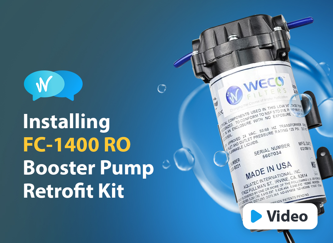
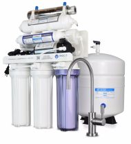
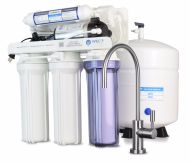
Instructions for Installing the FC-1400 Pump Retrofit Kit for Reverse Osmosis Systems

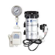
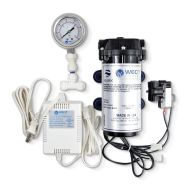
Package Contents
- Aquatec Pressure Booster Pump Qty 1
- Pump Transformer Qty 1
- High Pressure Switch (Tank Shutoff) Qty 1
- Elbow ¼" Stem x ¼" Tube Qty 2
- Elbow ⅜" Stem x ¼" Tube Qty 2
- Auto Shutoff valve ¼" Ports Qty 1
You Will Need
- Phillips Head Screwdriver
- Machine Screws #10-24 x 1" Qty 4
- Stainless Nuts #10-24 Qty 4
- Flat ¼ Washers Qty 4
Installation
Stop the water supply to the RO system by turning off the feed water adapter. Turn off tank ball valve and fully open the drinking water faucet to release water pressure in the system.
Disconnect all tubes going out from the RO system and place it on a convenient work surface. Disassemble the membrane and post filter. Remove all tubes, check valves, auto shutoff valves, flow restrictors and get access to the top of RO bracket.
Insert the two ¼" elbow stems into the pump.
Mount the pump on top of RO bracket and secure with screws. Using washers will reduce vibration & noise.
Notice the flow direction printed on the front of the pump and filter canisters. Outlet of the 1st stage (sediment) canister will connect to the inlet of the pump. Pump outlet will connect to the 2nd stage inlet (5m carbon) filter.
2nd stage canistor outlet should connect to the 3rd stage (0.5m carbon) inlet.
3rd stage canister outlet connects to the auto shutoff valve (ASO) inlet port side. Outlet of ASO will connect to membrane inlet side.
Permeate (filtered water) end of the membrane connect to the ASO inlet port side through a check valve. Make sure the flow direction of check valve is set away from the membrane.
Drain end of the membrane will connect to the under sink drain through a flow restrictor. Again check the flow direction away from membrane.
Remaining outlet of ASO valve connects to a union Tee branch. This branch also connect to the inlet side of the post carbon filter and the RO pressure tank though the high pressure switch.
Outlet of the post filter connects to the RO drinking water filter. Secure the membrane and post filter to the RO bracket using clips. T
Install the RO system under the sink and turn on the water supply. Check for leaks.
Booster Pump Retrofit Kit Installation

Plumbing and Wiring Diagrams
The high pressure switch shuts the pump off when the tank pressure exceeds 40 PSI.
Notice
Do not subject the pump to freezing temperatures, rain or direct sunlight while in operation.
Pump will not stop forward flow of water even if the motor is turned off if there is sufficient feed water pressure. Make sure the ASO valve is plumbed in using instructions above as a positive mean of shutting off the water supply.
Only qualified electricians per local and state codes should do electrical wiring.
Do not use with water that is microbiologically unsafe or of unknown quality.